


Specifying a gate valve for a European or export pipeline usually comes down to more than DN, body material, and pressure class. Before you issue a purchase requisition, you also have to get the face-to-face pattern right — and that is exactly where the DIN/EN designations F4, F5 and F7 start to matter.
If you mix them up, the valve you receive may not bolt into the existing line, or it may sit too long and clash with adjacent equipment, pumps, or supports. In this guide we walk you through what each pattern means, how their lengths and flange ratings differ, and how to specify the correct one with confidence — drawing on the full range of DIN/EN gate valves we manufacture every day at Full-Think.
Face-to-face (often written FTF) is the distance between the inlet and outlet flange faces of a valve when it is in the fully open position. It is a fixed dimension set by standard — in your case EN 558 (and its predecessor DIN 3202) — not something you can negotiate on a per-project basis.
Why does it matter to you? Your piping spools, support locations, and equipment centers were all laid out around a specific FTF. If the valve you install is even a few centimetres too long or too short, you are looking at re-cutting pipe, adding spool pieces, or re-working the support structure. Getting the series right on paper is far cheaper than fixing it on site.
EN 558 defines several face-to-face series. For wedge gate valves the three you will encounter most often in European and export projects are F4, F5 and F7. Each maps to a specific EN 558 series and — critically — to a specific flange pressure rating.
F4 corresponds to EN 558 Series 14 (DIN 3202 F4). It is the shortest face-to-face of the three and is typically paired with EN 1092 PN10 / PN16 flanges. Because the body is more compact and lighter, F4 is the default choice where installation space is tight — water treatment, building services, and general low-to-medium pressure industrial lines. If your line was built to PN16 and space is limited, you will almost certainly be specifying F4.
You can review our DIN F4 short-pattern gate valve (PN10–PN16) for typical dimensions and material options.
F5 corresponds to EN 558 Series 15 (DIN 3202 F5). It is longer than F4 and is typically associated with PN16 / PN25 flanges. F5 is often treated as the “standard” mid-length pattern: it gives you a robust body and broad interchangeability without the extra weight and length of the high-pressure series. When a project standard simply says “DIN gate valve” without specifying, F5 is frequently what is meant.
See our DIN F5 gate valve (PN16–PN25) for the full specification.
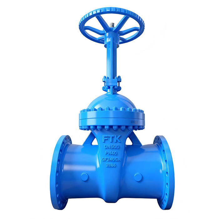
F7 corresponds to EN 558 Series 26 / 28 (DIN 3202 F7). It is the longest pattern and is typically paired with PN40 / PN64 flanges. The extended body accommodates the heavier wall sections and higher-rated trim needed for demanding service — oil & gas, steam, and power-plant applications. If your duty is high pressure, F7 is usually non-negotiable.
Our DIN F7 (PN40–PN64) gate valve covers the long-pattern range in cast steel.
| Pattern | EN 558 / DIN 3202 | Typical PN | Length | Typical use |
|---|---|---|---|---|
| F4 | Series 14 / F4 | PN10 – PN16 | Shortest | Water, HVAC, general industry |
| F5 | Series 15 / F5 | PN16 – PN25 | Standard | General process, default “DIN” spec |
| F7 | Series 26 / 28 / F7 | PN40 – PN64 | Longest | Oil & gas, steam, power |
The table below shows representative face-to-face lengths (raised-face, mm) so you can see how the gap widens as the nominal diameter grows. These are typical DIN 3352 values — always confirm against the latest standard and the manufacturer’s datasheet before you order.
| DN | F4 (mm) | F5 (mm) | F7 (mm) |
|---|---|---|---|
| 50 | 150 | 250 | 250 |
| 100 | 190 | 300 | 350 |
| 200 | 230 | 400 | 550 |
| 300 | 270 | 500 | 750 |
It is tempting to think “a DN100 gate valve is a DN100 gate valve.” In practice, F4, F5 and F7 are not freely interchangeable, and here is the reason that trips up most specifiers:
In short: you choose the pattern from the line you are connecting to — not from a catalogue preference.
When you sit down to specify, work through these five checks in order:
Not sure which pattern your line needs?
Send us your line’s flange standard, PN, and DN, and our engineers will confirm whether F4, F5 or F7 is correct — and flag any interchangeability risk before you order.
The face-to-face series is independent of stem type. Whether you choose an outside-screw-and-yoke (OS&Y / rising stem) or a non-rising stem (NRS) gate valve, the FTF is still governed by EN 558 / DIN 3202. What changes between the two is the installation height above the bonnet — NRS stays low, which matters in underground or ceiling-limited pits — not the length between flanges.
They are different standard families and are not directly equal. API 600 and ASME B16.10 define their own face-to-face lengths for ANSI-class gate valves (e.g. B16.10 “short” and “long” patterns), while EN 558 / DIN 3202 defines F4/F5/F7 for PN-rated valves. If you are bridging an ANSI-line project with PN-rated equipment — or vice versa — you must convert both the flange standard (ASME B16.5 vs EN 1092) and the FTF series, not just copy the DN across.
EN 558 and DIN 3202 specify the nominal FTF plus a manufacturing tolerance (typically a small plus/minus, tightening at larger DN). Verification happens during inspection and testing per EN 12266 / ISO 5208, where overall length is checked against the drawing and standard. When you receive a valve, a quick tape measurement of the flange-to-flange distance against the certified datum is one of the fastest ways to catch a wrong-series shipment before it reaches the spool.
The FTF series applies to the valve body envelope, so it is relevant regardless of seat type. Resilient-seated (often ductile-iron, drinking-water) gate valves are commonly built to F4 or F5, while metal-seated cast- or forged-steel industrial valves span the full F4–F7 range. The seat technology changes sealing and trim — not the face-to-face series you must match to the piping.
Every distinct series you install is a distinct spare you must stock, certify, and track. A plant that standardises on a single pattern (say F5 across a process unit) can hold one spare per DN instead of three. That simplifies obsolescence management, reduces working capital tied up in stores, and shortens shutdowns because the correct spare is already on the shelf and known to fit.
In European water and wastewater treatment, F4 (compact, PN10/PN16) dominates because space in pits and chambers is tight and pressures are modest. In oil & gas, steam, and power projects, F5 and F7 dominate — F5 for general PN16/PN25 process lines and F7 where PN40/PN64 high-pressure duty is required. If you regularly serve both sectors, expect to stock and specify across the full F4–F7 range.
About this guide: Prepared by the Full-Think Valve engineering team. Full-Think (FULL-THINK VALVE CO., LTD) is an ISO 9001-certified industrial valve manufacturer established in 2012, supplying DIN/EN, API and ANSI valves — including the F4, F5 and F7 gate valve series — to oil & gas, power, water and chemical projects worldwide.
Ready to specify your DIN gate valves?
Talk to Full-Think’s valve engineers for a quote on F4, F5 or F7 gate valves built to EN 558 / DIN 3202, with full material test reports and inspection documentation.
Keep building your specification know-how with these guides from the Full-Think team:
(All images are sourced from the internet. In the event of any copyright infringement, please contact us and we will remove the content promptly.)
 Optimized by Seraphinite Accelerator