
In the world of industrial fluid control, a P&ID (Piping and Instrumentation Diagram) is the blueprint of operational success.
Misinterpreting a single valve or connection symbol can lead to costly installation errors, unplanned downtime, or even hazardous operational failures.
This guide dives deep into the critical symbols that define P&IDs, with a focus on end connections, actuators, standardization, and practical application.
While valve types are the most recognizable symbols in a P&ID, end connections and actuators are equally critical. They determine how valves integrate with your pipeline system and how they are operated—directly impacting maintenance efficiency, system integrity, and operational safety.
The way a valve connects to a pipe dictates the system’s integrity, ease of maintenance, and suitability for specific pressure/temperature conditions. For Wholesalers and Importers, understanding these symbols ensures you source valves that match the exact installation requirements of your clients. Below are the most common end connection symbols, paired with their visual representations and key use cases:
| Connection Type | Symbol Description | Key Use Case |
| Flanged Connection | —| |— | High-pressure systems, easy disassembly for maintenance (e.g., refineries, chemical plants) |
| Threaded Connection | —|||— | Low-pressure applications, quick installation (e.g., instrumentation lines, small-bore piping) |
| Welded (Butt Weld) Connection | —X— | High-temperature/high-pressure systems, permanent connection (e.g., main pipeline transport) |
| Socket Weld Connection | —[ ]— | Small-diameter, high-pressure lines (e.g., instrument loops, sampling systems) |
Flanged: Represented by two parallel lines perpendicular to the pipe. Ideal for high-pressure systems where frequent disassembly (for maintenance or replacement) is needed. Common in refineries, chemical plants, and large-scale pipeline projects.
Threaded: Shown with small dots or specific hash marks at the connection point. Best for low-to-medium pressure applications, such as instrumentation lines, small-bore piping, and systems where quick installation is a priority.
Welded (Butt Weld): Indicated by an “X” or a direct line-to-line contact. A permanent connection designed for high-temperature, high-pressure environments (e.g., main oil/gas pipelines) where leakage risk must be minimized.
Socket Weld: Characterized by a small “step” or offset at the valve-pipe junction. Used for small-diameter (NPS 1/2 to NPS 2) high-pressure lines, such as instrument loops and sampling systems, where a compact, leak-tight connection is required.
Actuators are the mechanical or electrical components that translate control signals into physical valve movement. They are the “brain” of the valve, enabling remote operation, precise control, and emergency response—critical for modern industrial systems. For Brand Owners and Procurement Leads, specifying the right actuator type (and understanding its symbol) ensures your system operates efficiently and safely.
The Core Role of Actuators
Actuators bring immense value to industrial systems by: Enabling remote operation (reducing the need for on-site personnel in hazardous areas), ensuring rapid response in emergencies (e.g., shutdowns during pressure spikes), optimizing process precision (maintaining consistent flow/pressure), and reducing human error (automating repetitive tasks). For Distributors, knowledge of actuator functions helps you advise clients on the best solutions for their specific operational needs.
Identifying Actuator Types
In P&ID diagrams, the actuator symbol sits atop the valve body, clearly indicating its type. Below is a visual guide to the most common actuator symbols and their applications:
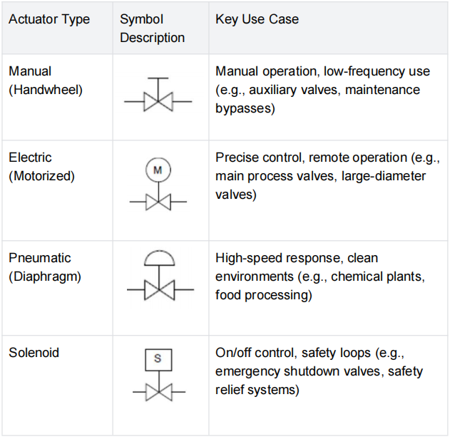
Manual (Handwheel): A simple “T” or circular handle. Used for valves that require infrequent operation, such as auxiliary valves or maintenance bypasses. Ideal for low-cost, low-complexity systems.
Electric (Motorized): A circle containing the letter “M”. Provides precise control and remote operation, making it suitable for main process valves, large-diameter valves, and systems where automation is a priority.
Pneumatic (Diaphragm): A half-circle or square connected to a signal line. Offers high-speed response and is ideal for clean environments (e.g., chemical plants, food processing) where electric actuators may pose a hazard.
Solenoid: Identified by the letter “S”, typically used for on/off control in safety loops. Critical for emergency shutdown valves (ESVs) and safety relief systems, where rapid response to process anomalies is essential.
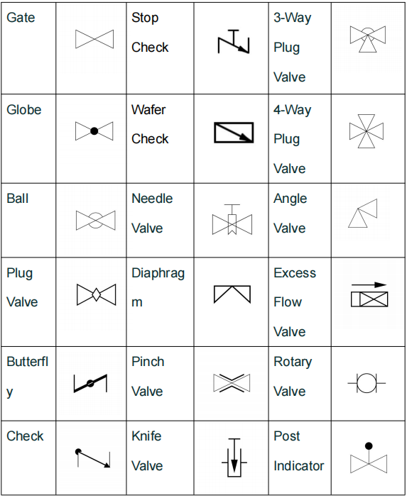
There are some common valve symbols and functions along with their symbolic representations
Fail-Safe Position Indicators
For Wholesalers, Importers, and Distributors, understanding fail-safe symbols is critical for ensuring the right specs are delivered. Fail-safe positions indicate how a valve behaves when power, air, or control signal is lost. These symbols are often paired with actuator symbols to provide complete operational clarity:
| Fail-Safe Symbol | Description | Use Case |
| FO (Fail Open) | Valve opens upon loss of power/air | Systems where continuous flow is critical (e.g., cooling water lines, ventilation systems) |
| FC (Fail Close) | Valve closes to prevent downstream flow during a failure | Safety-critical systems (e.g., fuel lines, chemical transfer, pressure relief loops) |
FO (Fail Open): The valve opens upon loss of power/air. Used in systems where continuous flow is critical, such as cooling water lines, ventilation systems, or processes where shutdown would cause equipment damage.
FC (Fail Close): The valve closes to prevent downstream flow during a failure. Mandatory for safety-critical systems, such as fuel lines, chemical transfer pipelines, and pressure relief loops, where leakage could lead to hazards.
P&ID standardization ensures that a diagram drawn in one country can be flawlessly executed, maintained, and modified in another—eliminating misinterpretation, reducing errors, and ensuring compliance. For Brand Owners and OEM/ODM Procurement Leads, standardized P&IDs streamline sourcing, reduce liability, and ensure consistency across your supply chain.
Below is a breakdown of the key benefits of P&ID standardization, visualized for clarity:
| Benefit Category | Benefit Level (1-10) | Key Description |
| Clarity & Consistency | 9 | Reduces catastrophic misinterpretation risk during installation/operation |
| Training Efficiency | 8 | Streamlines onboarding for new engineers/technicians |
| Cross-Team Collaboration | 9 | Facilitates seamless communication between mechanical/electrical/process teams |
| Compliance | 10 | Ensures adherence to ISO, ANSI, API industry standards |
| Maintenance Ease | 7 | Simplifies troubleshooting and replacement part sourcing |
| Cross-Industry Adaptability | 8 | Recognized across oil & gas, chemical, power, and pharmaceutical industries |
Clarity and Consistency: Reduces the risk of catastrophic misinterpretation during installation, operation, or maintenance. Standard symbols ensure every stakeholder—from engineers to technicians to suppliers—interprets the diagram the same way.
Training Efficiency: Streamlines the onboarding process for new engineers and technicians. Standardized symbols create a universal language, reducing training time and ensuring new team members can quickly contribute to projects.
Cross-Team Collaboration: Facilitates seamless communication between mechanical, electrical, and process departments. Standard P&IDs eliminate silos, ensuring all teams work from the same blueprint and reducing coordination errors.
Compliance: Ensures the system meets stringent ISO, ANSI, or API industry standards. For global Importers and Distributors, compliance with these standards is essential for market access and customer trust.
Maintenance Ease: Simplifies maintenance and troubleshooting. Standard symbols make it easy to identify components, locate issues, and source replacement parts—reducing unplanned downtime.
Cross-Industry Adaptability: Standardized P&IDs are recognized across industries (oil & gas, chemical, power, pharmaceuticals), making it easy to scale projects, collaborate with external partners, and adapt to new market needs.
Valves are the gatekeepers of your process—controlling flow, pressure, and direction to ensure safe, efficient operation.Understanding how valve functions translate to P&ID symbols is critical for specifying the right hardware and ensuring your system meets operational requirements.
Valves perform five critical functions in industrial systems, each directly linked to their P&ID symbols. Below is a visual guide to these functions and their real-world applications:
| Function | P&ID Clue | Example |
| Regulate | ⧓ (Globe) | Controlling steam temperature. |
| Divert | multimap (3-Way) | Directing flow to different tanks. |
| Protect | ⧖ (Relief) | Preventing tank overpressure. |
| Isolate | □ gate (Gate) | Shutting off a pump for repair. |
Start/Stop Flow and Regulate Pressure/Temperature: The most basic function of valves. Gate valves and Ball valves are used for on/off control, while Globe valves and Needle valves are designed for precise flow/pressure regulation.
Control Fluid Direction: Critical for directing flow to different parts of the system. Check valves prevent backflow, while 3-way and 4-way valves divert flow to multiple pipelines.
Protect Sensitive Equipment from Overpressure: Safety valves and Relief valves automatically open to release excess pressure, preventing equipment damage or catastrophic failure.
Isolate Components for Maintenance: Full-port valves (e.g., Gate valves) isolate specific equipment (pumps, tanks, filters) so maintenance can be performed without shutting down the entire plant—saving time and money.
Choosing the correct symbol is about matching the physical mechanism of the valve to its specific logic in the process flow. For example: A Ball valve symbol (a circle with a line through the center) indicates a quick on/off valve, making it ideal for isolating equipment. A Globe valve symbol (a rectangular body with a stem) indicates a valve designed for flow regulation, making it suitable for controlling pressure or temperature.
Valve tags are the “name tags” of P&IDs—providing critical information about each valve’s function, location, and specifications.
Valve tags follow a standardized format, making them easy to interpret across systems. A typical tag consists of two key parts:
| Tag Component | Description | Example |
| Functional Identifier | A letter indicating the component type | V = Valve, FCV = Flow Control Valve |
| Unique Number | A sequence or loop number for tracking | 101 = First valve in Loop 100, 205 = Fifth valve in Loop 200 |
V: The functional identifier (Valve). Other common identifiers include FCV (Flow Control Valve), SDV (Shutdown Valve), and MOV (Motor Operated Valve).
101: The unique loop or sequence number for tracking. This number links the valve to its location in the process loop, making it easy to locate, maintain, and replace.
Valve tags often include abbreviations to provide additional context about the valve’s function. Below are the most common abbreviations used in P&IDs:
| Abbreviation | Full Name | Function |
| FCV | Flow Control Valve | Regulates fluid flow to maintain setpoint |
| SDV | Shutdown Valve | Emergency on/off control for safety |
| MOV | Motor Operated Valve | Electrically controlled valve for remote operation |
| VGV | Vent Gas Valve | Controls venting of gas from the system |
| PRV | Pressure Relief Valve | Releases excess pressure to protect equipment |
In modern digital P&IDs, these tags act as hyperlinks, connecting the
user directly to maintenance databases, technical datasheets, and supplier information. This digital integration streamlines inventory management, maintenance scheduling, and procuremen.
What do end connection symbols show on a P&ID?
They show how valves connect to pipelines and match pressure, temperature, and maintenance needs.
What do actuator symbols tell us?
They show how valves are operated, such as manual, electric, pneumatic, or solenoid control.
What are FO and FC in valve fail-safe symbols?
FO means fail open, and FC means fail closed to ensure system safety when power or air is lost.
Why are standardized P&ID symbols important?
They avoid misunderstanding, ensure compliance, and improve teamwork, maintenance, and global project consistency.
Understanding the diagram is the first step; selecting the right hardware is the second. Why should you continue your inquiry with FULL THINK VALVE (FTK)? We are more than a supplier—we are your technical partner, dedicated to helping you navigate P&ID requirements and source valves that match your exact specifications.
Don’t leave your system to chance. Reach out to FULL THINK VALVE (FTK) today for a professional consultation or a tailored quote. Let’s build a safer, more efficient future together.
Mastering P&ID symbols is the key to unlocking efficient system design, operational safety, and cost savings. By understanding end connections, actuators, standardization, and valve functions, you can avoid costly errors, ensure compliance.